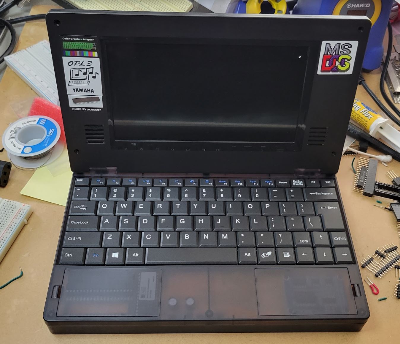
The Book8088 is an interesting little machine. It is essentially a 1980's computer in a laptop form factor.
With apologies to Sergey Kiselev, whom the manufacturers of the Book8088 did a little dirty, I couldn't resist ordering one myself to tinker with.
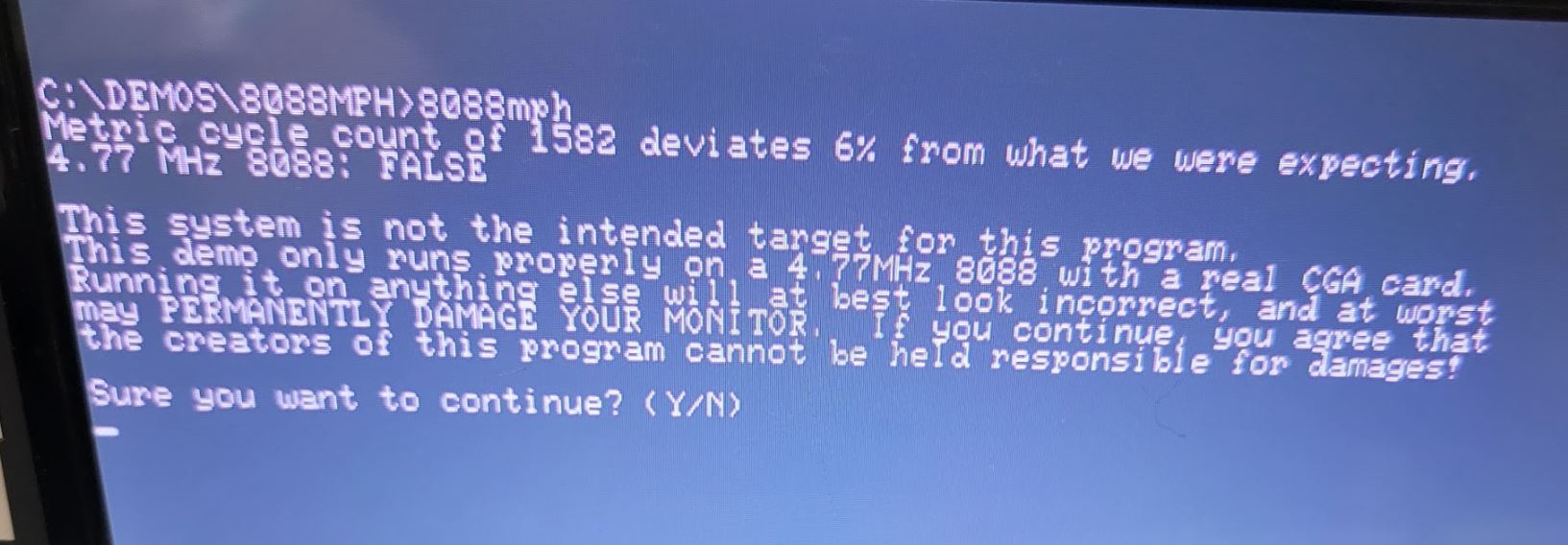
The Book8088 is trying hard to basically be compatible with the original IBM PC, containing some of the same or equivalent chips. It's natural to want to put it through its paces, and one of the best tests for IBM PC compatibility has to be the 8088MPH demo. If 8088MPH will run we must be operating pretty darn close to the original.
Looking at the specs of the Book8088, there's good reason to be optimistic. The machine supports a real 8088 CPU. Even better, there's a socketed CRTC chip, so the complex CRTC abuse the demo performs doesn't need to be emulated in any fashion.
My Book8088 came with an NEC V20 CPU. This CPU is a lot faster than the 8088, we'll need to replace it:
Additionally, the CRTC chip I received is not the same as you would find in an original IBM CGA card. Instead there's a Hitachi CRTC - let's replace it with a CGA-accurate Motorola MC6845:
Now, as it turns out, most of the demo does run, albeit in RGBI mode which loses out on all the cool composite artifact color effects. But most notably the famous Kefrens Bars effect does not display - the screen just goes blank. What's going wrong on the Book8088 vs a real IBM PC 5150?
As others have noted, even with an 8088 swap, there's something a little fishy going on.
DRAM Refresh DMA
The original IBM PC used DRAM - 'dynamic' memory that had to be periodically refreshed, or it would lose charge and subsequently its memory contents. IBM was trying to keep the costs of the IBM PC down, so decided to utilize some of the accessory chips that the PC had to perform the task of DRAM refresh rather than add dedicated circuitry to handle it. Therefore one of three channels of the system's timer chip and one of four channels of the system's DMA controller are dedicated solely to the task of refreshing memory.
By default, every 72 CPU cycles, the timer chip counts down to 0 and sends an output pulse to the DMA controller, triggering a DMA request which eventually pulls the READY line to the CPU low, potentially stalling the CPU if it is in the middle of a bus transaction. During this time certain address lines are strobed, which is all that is needed to refresh the memory cells.
This has a variable impact on system performance. If the CPU is primarily performing long, arithmetic instructions such as division or multiplication, it won't really slow things down at all. If the CPU is instead copying memory with a string instruction, or executing a sequence of very short instructions requiring rapid fetching, then the impact can be quite substantial. Averaged out, the 8088 CPU in the IBM PC is about 5% slower than it otherwise would be without DRAM refresh.
The Book8088 and many modern hobby PC clones like it usually forgo DRAM and its complications and instead use SRAM chips. The S stands for Static, and like the name suggests it does not require refreshing. Therefore we don't need to have this process going on at all, so we don't need to have timer channel #1 ticking away and we don't need DMA channel #0 configured for DRAM refresh, and our CPU can run 5% faster. Isn't that just a bonus?
Well, yes and no. When talking about compatibility with the original IBM PC, there were several software titles that made assumptions about the exact speed of the 8088 CPU, and they made those assumptions with the DRAM refresh performance impact baked-in. If we don't simulate DRAM refresh, we open ourselves up to compatibility issues.
The Kefrens effect in the 8088MPH demo is a good example. It is a perfectly cycle-counted effect. This effect does not tightly poll the CGA status register to determine when the CGA card is in hblank or vblank, or really where it is on the screen at all. It does not set up a normal screen resolution - instead, it draws a scanline at a time, 'racing the beam'. This is possible due to the fact that the CGA clock is an exact multiple of the CPU clock, so that a single CPU cycle equates to 3 pixels or 'hdots' on screen. Knowing that a single scanline takes 912 hdots to display means if we execute an effect somehow utilizing exactly 304 CPU cycles per scanline, that effect will run in perfect synchronization with the CGA card. And so that's exactly what the Kefrens effect does - it's some impressive coding.
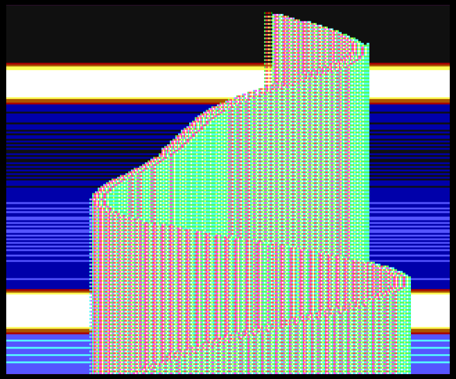 |
| Kefrens Bars in 8088MPH - it looks better in motion! |
The reason that this effect does not work on a stock Book8088 is that the painstaking cycle counting done for the effect takes into account the wait state cycles incurred by DRAM refresh DMA on the IBM PC.
Since the Book8088 isn't doing DRAM refresh, the corresponding wait states don't occur, the effect runs too fast, and quickly is out of sync with the CGA card. Vsync signals happen at the wrong times, and I imagine the LCD controller on the Book8088 gets very upset and refuses to display an image at all.
Can we just turn DMA on?
It would be nice if we could just program the timer channel #1 to the appropriate value, and set up DMA channel #0 like the BIOS does, and then DRAM refresh would operate as it does on the IBM PC, just harmlessly addressing the system's SRAM but making our 8088 CPU operate at the correct speed.
We can write a short assembly program that attempts to do just that, and assemble it to 'startdma.com':
; startdma.asm
; begin DRAM refresh DMA if for some reason your BIOS didn't

cpu 8086
org 100h

%include "macros.asm"
%include "library.asm"

main:

begin:  jmp start

        e_init_dmac         equ 03h     ; Initialize DMAC initialized
        dmac_ch0_addr_reg   equ 00h     ; DMAC channel 0 base addres (W)
        dmac_ch0_count_reg  equ 01h     ; DMAC channel 0 word count (W)
        dmac_mask_reg       equ 0Ah     ; DMAC single mask bit register (W)
        dmac_mode_reg       equ 0Bh     ; DMAC mode register (R/W)
        dmac_cmd_reg        equ 08h     ; DMAC command register

start:
        ; set up DRAM refresh on DMA channel 0

        mov     al, 0ffh                ; 16-bit memory refresh counter = 0FFFFh
        out     dmac_ch0_count_reg, al  ; write low byte
        nop
        out     dmac_ch0_count_reg, al  ; write high byte
        inc     ax                      ; al = 0
        out     dmac_mask_reg,al        ; unmask all DMA channels
        mov     al, 58h                 ; single mode, auto-init, read, channel 0
        out     dmac_mode_reg,al        ; DMA Mode register
        mov     al,0
        out     dmac_cmd_reg, al        ; DMA Command register

        ; set up pit channel #1 DMA timer

                pit_set_mode 1, PIT_RWM_LSB, 2, 0   ; Pit channel 1, LSB, RateGenerator, binary
        mov     al, 12h                             ; Default refresh value of 18
                pit_write_byte 1                    ; Write reload value to start timer

                dos_exit 0
        ret
We can run startdma.com and try 8088MPH, and... it makes no difference whatsoever.
If the designers of the Book8088 didn't really consider this to be an issue, it's quite possible they didn't bother to connect the output of the timer channel #1. Helpfully, ArsTechnica released
schematics for this system. Let's take a look:
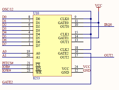 |
| The Book8088 timer schematic |
Well, drat. Just as we feared, the output of timer channel #1, the "OUT1" pin, isn't connected to anything. At least they were kind enough to connect the channel #1 clock input and the gate pin, so the timer channel is usable and can be programmed, but it won't ever trigger the DMA controller.
Over on the DMA controller, we see a similar situation:
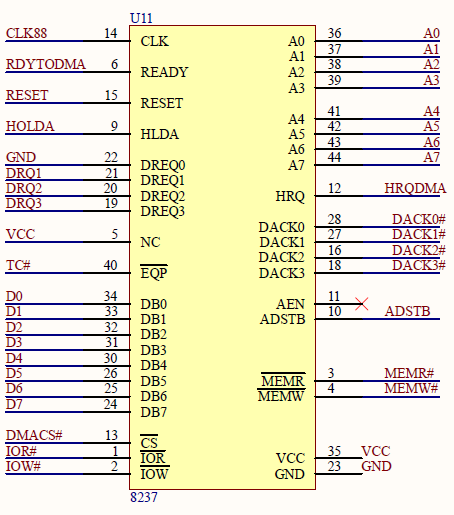 |
| The Book8088 DMA schematic |
The "DREQ0" pin that would normally connect to the timer's OUT1 pin is tied to ground.
We can physically fix this by reconnecting the timer and DMA controller, although that ground connection is a bit of a pain - we'll need to cut that trace.
Fixing the Book8088
The DMA controller is a Renesas CS82C37A , a CMOS variant of the original Intel 8237A Programmable Interrupt Controller. It is in a 44-PLCC package. Taking a peek at the white paper shows us the pinout:
 |
| DMA controller pinout |
DREQ0 is Pin22. We just need to look at the helpfully supplied PCB diagram:
 |
| DREQ0 pin |
Unfortunately, this pin is connected to a rather wide trace with a via to ground, making it a bit of a pain to cut, but thankfully there is enough access to the side of the socket so is fairly straightforward, as long as we are careful.
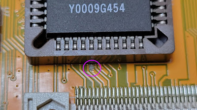 |
| Scrape the trace off before the via here, carefully. |
Use a continuity checker to verify that this pin is no longer connected to ground. Even a tiny sliver of trace can cause issues.
We will also need the DACK0 line, pin #28, for part of our DRAM refresh logic. This pin runs out to the ISA connector. This is an odd choice, since with DREQ0 connected to ground, the DACK0 line isn't very useful.
This being a surface-mount socket, our options for attaching our wires are a little limited. If we take stranded, 28 gauge wire, we can effectively drape them across the contacts of the empty socket, then push the chip back in on top of them. A gentle tug proves these connections reasonably secure. Be sure to check there is no connectivity between adjacent pins - the stranded wires can splay out and potentially short.
DREQ0 will go over to the timer chip, but it can't connect to the output of timer channel #1 directly. The timer is driven in Rate Generator mode, which stays high most of the time, dropping low on a 1 count for one tick. DREQ0 is level-triggered; if directly connected, DRAM refresh DMA would run constantly, and our PC would be much slower than intended.
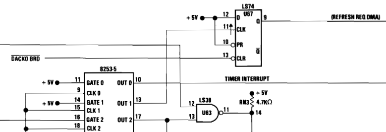 |
| The IBM 5150 DREQ0 logic circuit |
Instead, DREQ0 is driven by the output of a 74LS74 flip-flop, which is clocked by the channel #1 output. When there is a low to high transition of the timer output, the flipflop will take its input - tied to 5V, and output it on Q, sending our DREQ0 signal to the DMA controller. Notice the reset line is tied to DACK0; once the DMA controller acknowledges the DMA operation, the DREQ0 line will drop low. This ensures we only perform one DMA operation per timer terminal count.
This is easy enough to wire up if you happen to have a 74LS74 lying around:
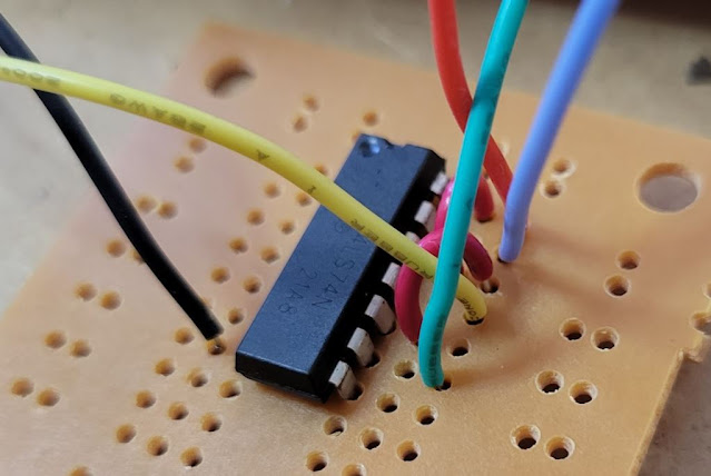 |
| The DREQ0 74LS74 flipflop |
The red wire is our 5V line, tying the D and PR lines to VCC; DACK0 comes in on our periwinkle wire and DREQ0 on the seafoam green wire. The timer channel 1 comes in on the yellow wire, and of course, black is our ground. If we trim the little breadboard, it fits pretty nicely in the bare spot beside the CGA ROM. I stuck it on with a square of double-stick gorilla tape:
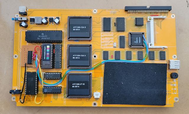 |
| The final assembled DRAM refresh DMA circuit |
Testing
Let's try the MIPS 1.20 benchmark first, to see how we square up against the baseline of an IBM PC.
Before running startdma, we can see we are about 5% faster than baseline:
After, we're right on the money:
Let's try the 8088MPH CPU test. It will certainly complain if we aren't running at the right speed, and without startdma, it does:
After, 8088MPH is content with our CPU speed:
The real test however, is to see if the cycle-counted Kefrens Bars effect works.
And it does! It's a shame we can't enjoy 8088MPH properly without a composite display, and the Book8088 doesn't have any sort of video-out, composite or otherwise. Maybe we can add one?
You might be curious about the 'sequel' to 8088MPH as well -
Area 5150. As it turns out, the final two effects are a bit trickier. Even with our DMA fix, they still show a black screen. It's possible that the Book8088's CPLD-implemented CGA logic isn't up to snuff - but I haven't given up hope.
Stay tuned :)


Glorious article, and and its impressive how much closer you could bring the Book8088 to an original IBM PC!
ReplyDeleteAs you seem the person who knows most about the CGA chip in the Book8088, I have a technical question. On my Book 8088 (V1), the display output makes some trouble: sometimes but not always, the screen is not aligned so that it misses the first half centimeter of the screen, and when it switches to graphic modes, I get some random distortions, worst is Win 30, and some games crash after a while. I expect this is not to be in general the case, so there might be a chip faulty. Would you expect it the CRTC chip or the CGA chip? If the latter, any idea which exact model this is so that I could try to find a replacement?
The alignment issue is a problem on all Book 8088 v1's. I suspect the LCD controller has a difficult type syncing to the CGA's output and they were not able to find a good solution. You can repeatedly type 'mode 80' to try to fix it, but it may revert on the next mode change.
DeleteThere's even a hotkey hardcoded into the keyboard controller to address this... If you type Fn+F7 it will type 'mode 80' and hit enter for you. Good if you need to mash it a few times.
Your crashing issues seem unrelated to this, but I couldn't really speculate as to what is causing them. If you are using the included AC adapter, I would recommend finding a suitable replacement. The adapter is extremely low-quality, potentially even dangerously so. It could definitely cause system instability.