In a previous article, I described a simple state machine to explain the prefetch behavior and miscellaneous observed bus delays of the Intel 8088. I now believe that the model I described there - although successful in modelling the 8088's behavior - was unnecessarily complex. There are in fact far fewer legitimate bus "delays", and they do not relate to internal state transitions. I have also slightly revised my description of the BIU's prefetching logic - I now believe that the prefetching decision happens at the end of T2, instead of the beginning of T3. There may not be much of a distinction between the end of one cycle and the beginning of the next, but it lines up better in our new diagrams.
Introduction
If you were interested enough to click on this article, you are probably already familiar with the 8088's bus cycle timings. A single bus cycle on the 8088 takes a minimum of 4 CPU cycles, consisting of 4 T-states numbered T1, T2, T3 and T4. Wait states (Tw) can be inserted between T3 and T4 via manipulation of the CPU's READY line to accommodate access to slower devices, but in general, the 4 T-states have been the demonstrable model of the 8088 for decades.
 |
iAPX 86/88 User's Manual, pg 4-5 |
Diagrams such as the above have appeared in innumerable manuals, web references and computer science textbooks. It is no surprise then that emulator authors attempted to construct the logic and timings of their emulators around a 4-cycle bus cycle time. Unfortunately, this is an incomplete picture. For whatever reason, Intel was averse to advertising the true bus cycle time of the 8088 in their official documentation, and so this incomplete model has persisted to this day.
Ken Shirriff, in his analysis of the 8086's silicon, was the first to document this, to my knowledge, on his blog entry, Reverse-engineering the 8086 processor's address and data pin circuits.
He states,
There [are] two undocumented T states that are important to the bus cycle. The physical address is computed in the two clock cycles before T1 so the address will be available in T1. I give these "invisible" T states the names TS (start) and T0.
I originally missed the significance of this - it's casually mentioned as if it were an interesting, but ultimately trivial internal detail. However these cycles are fundamental to the timing and operation of the 8088. They are not quite "invisible" after all!
To properly emulate the 8088, you must account for at least a 6 cycle bus cycle time.
It seems farfetched at first - we know that we can execute NOPs back to back at the speed at which the opcodes can be fetched - that is 4 cycles for each byte-sized NOP opcode. So that would disprove this theory right out of the gate. The key that makes it possible is that the BIU is actually pipelined.
The Intel iAPX manual gave us a hint, even if it only mentioned the four conventional T-states:
A pipelined architecture. The only previously pipelining I was really aware of was the ability of the 8088 to execute the last cycle of an instruction on the first cycle of a new instruction, via the NXT microcode flag facility. But it turns out the 8088 is capable of pipelining the calculation of the 20-bit address for the next bus cycle while it is performing the first.
In retrospect, the need for additional bus cycles should have been obvious. Consider what happens on the T1 state of the 8088. On T1, the full, 20-bit address of the bus cycle operation is placed on the CPU's address pins, and the ALE signal - either directly or via the i8288, is asserted so that the address can be latched by motherboard circuitry.
Remember that this is a CPU that takes 3 cycles to add an immediate operand to a register. While it's true that the BIU has a dedicated adder to produce the 20 bit address (seen above on the right hand side at the top), before this adder can produce the address emitted on T1 it must first load the correct segment register and index register, and only then perform the shift and addition operation.
This takes two cycles, which Ken has named Ts and T0.
This makes it impossible that any bus request from the EU can result in a T1 immediately, even if the prefetcher is idle. Observationally, after mining a
dataset of over 3 million instruction executions, I found that the minimum delay between a EU bus request and the subsequent T1 is 3 cycles. This is just not usually noticed because much of the time during normal operation the EU is contending with the BIU's prefetch unit for the bus. One might naively assume that, if it were not for prefetch bus cycles getting in the way, an EU bus request might have been serviced faster - even immediately.
I am adding a third logical T-state to the two additional states already mentioned: Tr. This may or may not correspond to a physical state in silicon, but it represents the cycle on which either a prefetch decision or bus request from the EU is made. Therefore in the model I am about to describe, the total bus cycle time of the 8088 can be thought of as 7 cycles in total!
As a base example, lets look at our NOPs executing back to back. First, we will present the traditional model of a 4-cycle bus cycle time:
 |
| The traditional, incomplete bus cycle model |
Here we see NOPs executing back to back while the queue is empty. Although NOP is a 3-cycle instruction, they are lengthened here to four due to needing to wait an additional cycle for the the next NOP opcode to be fetched and read from the queue. We cannot read bytes out of an empty queue any faster than they are put in, so our NOPs all execute in four cycles. There's no evidence here of a longer bus cycle time than 4.
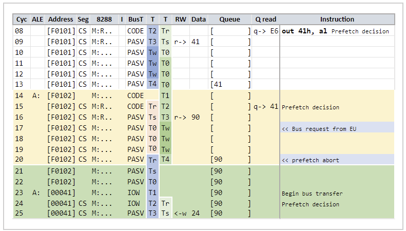
Let's look at an alternative diagram with the additional, pipelined T-states illustrated:
 |
| Our new logical 7-cycle bus cycle model |
At the end of T2, a prefetch decision is made. In this case, any possible Tr state is fleeting at best. Its entirely possible that Tr is only really meaningful for EU bus requests, but I include it here for consistency's sake, as it shows the cycle on which the prefetch decision is made. The bus cycle for the next fetch begins with the Ts state on the previous cycle's T3, so that a T1 can immediately occur after T4.
BIU Prefetch Logic
Let's take a moment to recap the logic of prefetching.
Prefetching is an automatic process performed by the BIU, where bytes from the code segment are read from memory and placed into the processor's instruction queue. This process happens proactively as long as prefetching is not suspended and there is room in the queue to place a new byte.
Prefetching can be suspended in certain scenarios:
- During the HALT state
- After execution of the SUSPEND microcode operation
- When the queue is full
A prefetch is typically started* at the end of T2 during the last byte of any atomic bus transfer. On the 8088, that is an important point, since word transfers are split into two byte transfers back to back. During the bus cycle in which the first byte of a word is being transferred, a prefetch will not be started.
*My previous article discussed prefetches as being "scheduled" - implying some latency between the decision to fetch and the initiation of the code fetch bus cycle. Now that we have a model of the full bus cycle time, there is actually no latency at all. Thus a "scheduled prefetch" isn't a concept we need. A fetch is simply started on a certain cycle or it is not.
A prefetch can be started in a few other scenarios:
- A FLUSH microcode operation is executed, resuming fetching from a SUSPENDed state.
- A byte is read from a full queue, making room for a new byte
- The bus is otherwise idle, and there is room for the queue for a byte to be fetched
A fetch can also be delayed, as a policy decision, at the end of T2 when the length of the queue is 3. This effectively represents a 3 cycle delay, but specific numbers need not be modelled - if we simply skip the prefetch decision on T2 when the queue is 3, then the fetch will be started on the cycle after T4, implementing our 3 cycle delay with no extra logic required. We will discuss this more in detail later.
A pending request from the EU on or prior to T2 will prevent a prefetch from beginning at the end of T2.
If a request from the EU is received on T3 or T4 after a prefetch bus cycle has commenced, the prefetch can be aborted on T4. This traditionally required modelling two Ti idle states known as a prefetch abort penalty. As we will see with our new model, no delays or penalty cycles are actually required.
Bootstrapping Prefetch
We can observe that a code fetch T1 cycle begins immediately after the 8088 completes the RESET microcode subroutine from power-on. Our previous model had to describe a state transition to explain the delay between the FLUSH command that initiates the CPU's first fetch and the actual T1 of the fetch:
 |
| RESET routine, old bus model |
In the diagrams I will be showing, a pink color indicates previously unexplained or state-modelled delays that are no longer needed.
If we simply enter the Tr state on FLUSH, then everything follows naturally, with no artificial delays:
 |
| RESET routine, new bus model |
Prefetch Aborts
Since a prefetch is normally started at the end of T2 of a bus cycle, a bus request from the EU prior to or on T1 or T2 will enter the Tr state and prevent a fetch from beginning during that bus cycle.
At the end of T2, a fetch bus cycle is started, and we enter the T3-Ts pipelined state. If an EU bus request is received now either on T3-Ts, or T4-T0, then the prefetch bus cycle can be cancelled, and a new bus cycle servicing the EU immediately begun.
Here is what this looks like under the traditional bus model:
 |
| The traditional 4-cycle bus model with its "prefetch abort" penalty cycles |
The picture is much simpler in the new model:
We can see that on T4, the EU bus request is immediately serviced. The previous cycles we explained as "penalty cycles" are simply the required Ts and T0 states to recalculate the new address for the EU bus cycle, with the work of the previous Ts cycle intended for a fetch discarded.
There is an effective delay here, in that the abort check only occurs on T4. Therefore if we moved the bus request from the EU one cycle earlier to T3, the cycle timings illustrated would be identical, with Tr held for two cycles.
This logic finally explains a paragraph in the Intel iAPX 86 88 User's Guide which had confused me since I first read it:
 |
| iAPX 86/88 User's Manual, 1-109 |
This paragraph, when read with the mental model of a 4-cycle bus cycle time, seems to contradict itself. It states that a prefetch abort results in two idle cycles, and yet, goes on to state that the maximum delay incurred is one cycle. Well, which is it? Is the delay two cycles, or one?
It's clear now - the maximum delay incurred is one cycle in the case where the EU request arrives on T3 and must wait for the abort decision on T4. But the two 'idle' Ti cycles mentioned are not really idle at all - they are the Ts and T0 states. Intel must have had their reasons for not wanting to disclose the reality of their 6-cycle bus access time, but left this passage as a clue.
Wait States
The CPU will normally attempt to perform the actual bus cycle operation, a read or a write, on T3 of the bus cycle. However, the addressed device can signal that is needs more time to respond via the CPU's READY line. When this occurs, wait states, or Tw cycles, are inserted between T3 and T4. This could conceivably have an affect on our bus cycles are pipelined.
In this example, 3 wait states have been injected into memory access, affecting the the fetch that occurs prior to the requested IO write operation.
It should be clear that a T0 state cannot proceed to T1 until T4 has completed - the BIU can simply hold on to the computed address for the next bus cycle, repeating T0 until T1. Likewise, since a prefetch abort decision happens on T4, the wait states add to the effective latency of the EU bus request made on the first Tw state. There is effectively now a four-cycle window in which the EU could have made its request without affecting overall cycle execution time of this instruction.
Explaining the 8088 Bus Delays
With a 4-cycle bus cycle model, the 8088 encounters confusing delays at times that cannot be accounted for by microcode execution or an active bus transfer. Convoluted logic is required to handle them. Properly modelling the a 7-cycle bus cycle time explains these delays simply in every circumstance I have encountered. Here we will examine a few of them.
SUSPEND "Delays"
In a 4-cycle bus cycle model, it can be observed that when prefetching is disabled, either via a full queue, or via the SUSPEND microcode routine, that EU bus requests appear delayed. These delays required contrived state logic to explain previously. Now, they are simply the result of the full 7-cycle bus cycle time being exposed since there are no fetches to pipeline the first 3 cycles in.
The CALL FAR instruction is interesting in that it issues the SUSPEND microcode routine, but then issues bus requests while the prefetcher is suspended. On the left, we see the mysterious delays in pink. On the right, we simply see the true, 7-cycle bus cycle timings, with no delay states or state transitions required.
 |
| Old vs New Bus Model |
Queue Full "Delays"
A similar phenomenon occurs when the instruction queue is full, which affects long running instructions that make memory accesses, such as string operations like REP MOVSB. Every read and write that the instruction makes while the queue is full (and thus prefetching suspended) appears to be delayed by 3 cycles.
Under our new model, these delays vanish, each bus request entering the Tr state immediately when requested:
While we are on the topic of MOVS instructions: On the 8088, REP MOVSW is much faster than REP MOVSB, despite the 8088 being limited to an 8 bit data bus, which one might assume would preclude any major advantage of one over the other. Part of that is due to halved overhead in the microcode loop logic, but that is still only 3 cycles per iteration - loop overhead alone does not account for the difference.
If we look at the published cycle times for REP MOVSB, we can see that it listed as 17 cycles per iteration. With 3 cycles of microcode loop overhead, that leaves 14 cycles to actually move two bytes - matching our new model of 7 cycles per bus cycle. A word transfer, however, can take advantage of the BIU pipeline for the second byte, completing in only 11 cycles. 11+11+3 = 25 cycles per iteration, again matching published timings. Therefore, a good percentage of the speed advantage of MOVSW on the 8088 is due to bus pipelining.
Prefetch Policy Delays
During a code fetch cycle, at the end of T2 when a prefetch decision is made, the length of the queue is examined. If the queue length is 3, a prefetch is not started.
Under the old bus model, this required modelling a 3-cycle prefetch delay:
Under our new model, we simply do not begin a fetch on T2 when the queue length is 3. After T4, a fetch will begin if the queue is no longer full.
Our three cycle 'delay' is now simply the exposed, full 7-cycle bus cycle.
If we did not have this special policy, were in an active code fetch bus cycle, and the queue length at the end of T2 was 3, then it can be assumed that - barring intervention from the EU - on T4 the queue would be filled by the current code fetch. But we would have already begun a new code fetch bus cycle - without any room to put the byte we intend to fetch!
Thus this policy decision prevents a scenario where a code fetch cycle is begun where there is a possibility that it could not complete. After T4, we know whether we can safely fetch again. For this reason, the policy decision is only applied during a code fetch cycle.
Interrupt Timing
Interrupt handling is a microcoded subroutine - just like any instruction, the request for an Interrupt Acknowledge bus cycle is issued from the EU, and so, interrupts follow the same rules. However, there is additional latency incurred by loading and beginning the interrupt microcode routine.
 |
| Interrupt handling during NOP on NXT |
On cycle 57, the INTR line off the CPU was asserted. However, this has no immediate effect until the next cycle rising edge, where an internal latch is set (See Ken's excellent article on
interrupts on the 8086)
This latch is applied with other logic to result in an internal INTR signal, if interrupts are not disabled*. This signal is then checked when the CPU is about to fetch the next instruction byte.
*Interrupts can be disabled via the Interrupt CPU flag, or temporarily after certain instructions such as STI or access to segment registers.
Intel's documentation is not terribly specific about when interrupts are checked, simply stating that it is done at the end of an instruction. Experimentally, we can show that the presence of an NXT flag* can affect interrupt timings. If there is a byte available in the queue, the NXT flag on the microcode instruction will instruct the BIU to read it and prepare it as the next instruction. Before this is done, however, the internal interrupt signal is checked. If an interrupt is to be processed, the byte is not read.
*The NXT flag is a signal to the CPU from the EU that the next microcode instruction to be executed is the last microcode instruction. This allows the next instruction byte to be read from the queue, if available, and the process of preparing the next instruction to commence one cycle earlier than normal. This enables a one-cycle execution pipeline, where the last microcode instruction executes on the first cycle of the new instruction - which would have otherwise left the EU's microcode execution unit idle.
The NOP example above shows the effect of NXT. The next cycle is spent preparing the interrupt microcode routine, and then on cycle 60 the microcode executes a request for an interrupt acknowledge cycle. This enters the Tr state as normal.
Let's look at an example where the INTR line is asserted one cycle later in the NOP instruction.
 |
| Interrupt handling during NOP on RNI |
Here the INTR line is physically asserted on cycle 15, and latched on the leading edge of 16, in time for the RNI flagged microcode instruction to execute. Like NXT, RNI will attempt to process the next instruction byte, but checks the interrupt status first. Finding an active, enabled interrupt signal, we prepare to execute the interrupt microcode on cycle 17. Note that the BIU is not really aware of this, and so on T2, it starts a new code fetch bus cycle.
The request for an interrupt acknowledge bus cycle on cycle 18 then follows standard prefetch abort logic. On T4, the abort check occurs, and only then is the interrupt acknowledge bus cycle begun.
We end up with completely different interrupt timings based off a single cycle difference in when INTR is asserted, due to the effect of the NXT flag.
An instruction such as INTO (when the overflow flag is not set) has identical cycle timings to NOP, however does not have any NXT flagged microcode instructions. In this case, we observe no difference between INTR being asserted on any cycle of INTO prior to RNI.
Halt Timings
We've addressed pretty much every previously odd bus scenario on the 8088, leaving us to address the timings around the HLT instruction and its related halt state. Unfortunately, our new model does not significantly clarify the situation here. HLT is not a microcoded instruction; it is implemented with a series of specialized logic gates.
The HLT instruction is therefore a state machine that proceeds independently of the BIU logic, which continues independently. This has some interesting ramifications.
First, it is possible to fully prevent the one-cycle HALT bus state from occurring if an interrupt is already pending, or INTR is raised high during the first clock of the HLT instruction:
 |
| HALT bus state suppressed by early INTR |
The situation is different if INTR is asserted even a single cycle later:
 |
| Fastest HALT resume timing |
In this case we do see the HALT state; however we resume from halt a mere two cycles later.
When resuming from halted state, the interrupt logic may occur more or less as we have already established. The INTR line goes high, is latched on the next rising edge transition of the CPU clock, the microcode routine for interrupt is loaded, and a bus request for an interrupt acknowledge cycle is made. This enters the Tr state, and we begin T1 of an interrupt acknowledge bus cycle exactly when anticipated:
 |
| "Normal" halt resume timings |
However, it is often observed that T1 of the interrupt acknowledge bus cycle is delayed by one cycle relative to INTR. This phenomenon has not yet been conclusively explained.
 |
| "Delayed" halt resume timings |
I propose the following theory: If we follow the logic Ken describes in his blog, we read that HLT logic waits for T2, whereupon it disables prefetching. However, depending on current bus activity, T2 may occur before HLT can execute this check, and thus a prefetch bus cycle is started before HLT can disable prefetching. It is this scenario that appears to cause a one cycle delay when resuming from a halted state. This could simply be the result of the incomplete fetch cycle, but its possible that the states of the internal latches that drive the halt condition could be responsible.
Conclusion
After attempting to piece the puzzle of the 8088 together over the past year, I'm extremely satisfied to finally have a simple, consistent description of the chip's bus timings and prefetch behavior. I can only apologize for publishing an incomplete model in my previous article - I hope it did not lead too many people astray. The key to this simplified model just required accepting something contrary to accepted wisdom. It is often difficult to look past our initial assumptions: in this case, that a bus cycle on the 8088 must be four cycles long.
A big thank you, again, to Ken Shirriff and
his excellent blog. If you aren't following it, you're missing out!
.


In the diagram about REP MOVSB, there is a prefetch start on cycle 35, although the prefetch queue already has 3 bytes. This seems to contradict the claim that no "pipelined prefetch" is started while the queue length is 3. It is quite likely that the suppression of pipelined prefeteches is indeed to prevent the risk of a prefetch in which the result could not be stored, and in this case, the concurrent bus cycle started at 33 is an EU cycle that would not fill the queue.
ReplyDeleteI suggest an even simpler way of expressing "the queue is at length 3 and the current cycle is a code cycle, so no prefetch is started" by introducting the concept of a "reserved" slot in the queue: Some time during the prefetch cycle, the entry in the prefetch queue already gets "reseved", i.e. it counts as full regarding the prefetch decision logic, but is not yet "filled", i.e. it counts as empty regarding the logic transferring the opcode to the EU.
As I consider it, calling the 4-cycle bus timing of the 8088 "wrong" is a question of wording. In my oppinion, the datasheet does the correct thing: It describes how the processor interfaces to the other components, because that is what most people trying to build a 8088 computer actually want to know. The externally visible part of the bus cycle indeed takes 4 clocks, and it can occur back-to-back, so the 4-cycle model is very useful for mainboard designers. As such, I wouldn't call the datasheet description wrong, though you might argue that it might be "misleadingly simplified". The misconception this post clears up is equating the externally visible bus cycle with the complete internal bus cycle. I will keep thinking about the 8088 having an (external) bus cycle of 4 clocks, but thanks to your post, I understand that the internal management of the bus cycle takes 7 clocks.
You are correct, the policy decision only applies during CODE fetch cycles as we do not have to worry about filling the queue on an EU-initiated bus cycle, and that is how I have it implemented in MartyPC. I omitted that condition and will make a correction.
DeleteYou quote the word "wrong" but it does not appear in this article. I deliberately avoided using the term, in favor of "incomplete". When I was originally thinking about what to name these cycle states, I did not even want to call them T-states until I reviewed Ken's articles and discovered he had already discovered and named them. I was thinking about naming them A0-A2 for 'Address Cycle'. We could then think in terms of two phases, an address cycle and a bus cycle.
It is true that from a bus perspective the Tr-T0 states are silent, and that the time from first bus signal (ALE) to T4 is and has always been 4 cycles, but I will argue that a short explanation of the total bus access time within Intel documentation seems like an odd omission given the extremely detailed timing diagrams otherwise provided.
Thanks for the feedback!