 |
| A V20 CPU, courtesy of Konstantin Lanzet (CC) |
The NEC V20 was a 16-bit CPU released in 1984. It is pin-compatible with the Intel 8088, and clones the 8088's instruction set. It also includes newer instructions that had been introduced two years prior by the Intel 80186 and 80286, but does not include the latter's protected-mode features.
Besides the 186 instruction set, NEC also added new opcodes and instruction prefixes of their own, enabling performance enhancements for software that could detect or require a V20.
NEC also incorporated various other improvements Intel had made in the 80186, namely hardware support for address calculation and for division and multiplication. The former was a big benefit overall, as it could decrease the execution time of any instruction utilizing a memory address operand.
The V20 was one of the first 3rd-party, drop-in CPU replacements for the PC. An owner of an original IBM 5150 could pull the 8088 out of their motherboard's CPU socket, install a V20, and enjoy improved software support and a decent performance increase at a rather attractive price. Upgrade kits were sold for as little as $15.95. Of course, this made Intel unhappy, and lawsuits followed.
In ideal situations, the V20 could achieve performance somewhere between an 8086 and a 286 - making it an attractive upgrade indeed. For owners of the 8086, the V30 was offered as a similar upgrade.
Over the past few years I have done extensive research on the 8088. I thought I would spend some time now poking around at the V20, which has yet to be so thoroughly explored. I am not Ken Shirriff, so no in-depth, gate level analysis from die photos here. Just the information I can glean from controlling the CPU via an Arduino microcontroller. Speaking of which...
Improving the Arduino8088
One of the things that spurred my curiosity over the V20 is an improved Arduino8088 board. The board has been modified for 3V operation, and now includes a speaker and status LEDs. The software that drives it has been rewritten for a much faster Arduino - the Arduino DUE (The GIGA has since been released and is much faster in turn than the DUE, but that's a future project).
 |
| Arduino8088 v1.1 |
The MEGA that I used to generate the original 8088 test suite used an ATmega2560 CPU clocked at 16 Mhz. By comparison, the DUE has an 84Mhz SAM3X8E ARM Cortex M3. This by itself is a nice perk; but the actual biggest benefit of switching to the DUE is support for native USB serial. This runs at 480Mbps compared to the maximum of 2Mbps possible via the MEGA's USB to serial conversion chip. Considering a single byte has to be sent and five bytes received as acknowledgment to clock the CPU and retrieve its state, the serial control protocol was the main bottleneck. At 2M baud, the protocol itself limits us to a theoretical maximum clock speed of 333Khz, and that's not counting latency, GPIO state change delays, and other issues which make the effective clock rate far lower still.
Overall, the DUE ends up being about 7 times faster running validation tasks than the MEGA, and I believe even more optimization is possible. Generating a test set of 10,000 opcode executions used to take over 20 minutes; now it takes only 3.
V20 Reset Vector
A quick note about the V20 reset vector. The original 8088 has a reset vector of FFFF:0000. Intel changed the reset vector to F000:FFF0 on the 286. The V20 keeps the same reset vector as the 8088, at FFFF:0000. This is important for implementing proper wrapping behavior. A popular set of '186' test ROMs by Artlav actually assumes a 286 reset vector, so keep that in mind.
V20 Mnemonics
NEC defined their own mnemonics for the 8088 ISA, probably for legal reasons; we will ignore NEC's naming conventions except when discussing V20-specific instructions. If you're curious as to what NEC named things, here is a translation table from Intel to NEC naming conventions:
Fuzzing the V20
The NEC is less resilient to undefined instruction forms than the 8088. The 8088 will not stop executing even if fed a random stream of bytes (assuming we filter HLT). The 8088 has no concept of an illegal instruction, although the operations it performs for certain invalid instruction encodings may be of questionable usefulness. The V20, in contrast, is a bit more fussy. It doesn't have an illegal instruction exception either, but certain instruction forms can simply cause the V20 to halt so we must do a bit of masking when fuzzing.
With our new "ArduinoV20" in hand, we can explore the behavior of V20 instructions, both defined and undefined.
V20 Opcode Notes
0F
The V20 does not perform the dubious POP CS like the 8088 does. As Intel did on the 286, the V20 repurposes 0F as the first byte of a set of extended two byte opcodes. We'll take a look at those in more detail below.
60-6F
On the 8088, 60-6F are aliases for the relative jump opcodes 70-7F. Not so on the V20. Several new 186+ instructions live here, as well as a few new instructions and two prefixes unique to the V20.
60 PUSHA
(186+) Pushes the 8 main 16 bit registers to the stack. The value pushed for SP is the value of SP before any register is pushed.
61 POPA
(186+) The complement to PUSHA, popping the registers off the stack (except for SP, which is ignored)
62 BOUND
(186+) BOUND takes a modr/m byte, and its memory operand consists of two signed words, giving this instruction a unique operand type. The value of the register operand is interpreted as a signed word index. The two signed words of the memory operand are interpreted as a starting and ending bounds. If the index is not greater than start and less than end, INT5 is executed.
63 Undefined
63 is an undefined opcode that takes a 16-bit modr/m operand which it reads and then and spends approximately 60 cycles doing nothing. It does not modify any registers or flags. This turns out to be actually pretty useful for test generation, as during those 60 cycles the instruction queue is filled without any side-effects. This allowed me to execute and generate tests for instructions from a fully prefetched state.
64 REPNC
(V20) The V20 defines a new prefix for use with string operations. With this prefix, a string operation will run until CX is exhausted as normal, but with an additional exit if the carry flag is set. This prefix along with its twin REPC are intended for use with the string comparison instruction CMPSB, although it will affect all string operations except for INS and OUTS for which it acts like a plain REP prefix. If carry is set at the start of the instruction, one iteration will still be performed - carry is only checked after each iteration.
65 REPC
(V20) Similar to REPNC but with inverted carry flag logic, REPC will repeat the string operation as long as carry is set. One iteration will always be performed - carry is only checked after each iteration. Acts like a regular REP prefix when attached to INS or OUTS.
66-67 FPO2
(V20) The V20 defines two additional
ESC opcodes here for use with a floating point math coprocessor, which it calls
FPO2. An 8087 won't know what to do with these; but NEC had planned its own math coprocessor, the
UPD72191, which might have been designed to work with these additional opcodes.68, 6A PUSH imm
(186+) Pushes an immediate value to the stack, either as 16-bits (68) or 8-bits (6A). In 8-bit mode, the immediate operand is sign-extended.
69, 6B IMUL imm
(186+) This form of multiplication marks the first appearance of three-operand instructions, taking both a modr/m and an immediate. The product is constrained to a single register.
6C, 6D INS
(186+) When utilized with a REP prefix, these instructions act like the string operation MOVS, except using an IO port specified by DX as the source and ES:DI as the destination. DI is updated per iteration.
6E, 6F OUTS
(186+) When utilized with a REP prefix, these instructions act like string operations with a source of DS:SI (segment-overridable) and an IO port specified by DX as the destination. SI is updated per iteration.
82 Group 1: Bitwise Operations
Like on the 8088, 82 appears aliased to 80, performing bitwise operations on an immediate byte operand.
8E MOV sreg, r/m16
POP CS may not be implemented, but the V20 happily overwrites CS if specified as the register destination in this form. NEC documentation states such a form is undefined.
8F POP
The forms of this instruction with modr/m reg field !=0 are undefined. On the 8088, their behavior is strange - on the V20, their behavior is
completely broken. The POP
instruction itself will appear to act as a
NOP, but it will likely break the following instruction by injecting the stack memory reads that didn't occur during
POP itself. Bizarre. This was known about in the day; see this
text file. Some further discussion of this can be found
here.
A6, A7 CMPS
One peculiar difference to the 8088 here is the order in which CMPS on the V20 accesses its operands. When prefixed by a REPE/REPNE, ES is read first, and then the overridable DS segment is read second. When not prefixed, CMPS behaves like an 8088 and reads from DS first. This is an odd quirk - if it always read from ES first one might propose that it was due to shared microcode between CMPS and SCAS. Does the V20 have different microcode for prefixed and non-prefixed CMPS instructions? Without decoding the V20 microcode, we can only speculate.
C0-C1 Bitwise Operations
(186+) C0 and C1 are now new group instructions for bitwise operations with an immediate operand. Unlike on the 80186, the immediate byte operand is not masked. Extension 6 performs SHL.
C8 ENTER
(186+) ENTER was designed as support for creating stack frames in higher-level languages such as Pascal. Intel documentation states that the nesting level is determined by the second immediate operand modulo 32. The V20 apparently ignores this detail and uses the unmasked value of the immediate.
D0-D3 Bitwise Operations
Similar to
C0-C1, The V20 does not mask the value of CL used as a count with
D2-D3. The 8088 has
undocumented instructions at extension 6 here;
SETMO for
D0-D1, and
SETMOC for
D2-D3. The V20 does not perform either; extension 6 is aliased to
SHL.
D4 AAM, D5 AAD
These BCD operations take an immediate byte operand representing the number base. Most assemblers will assume a value of 0A (decimal 10) to represent base 10 or traditional decimal values. The 8088 can actually accept any value for the immediate base for both D4 and D5. The V20 honors the immediate value for AAM (D4) but ignores it for AAD (D5). If an immediate value of 0 is provided to AAM , the AH register is set to FF and AL is unchanged, but the Sign, Zero and Parity flags are updated against the current value of AL.
D6 XLAT
The 8088 has an undocumented instruction SALC here. The V20 does not implement it. At first glance it would appear D6 is an alias to D7, as it seems to perform XLAT correctly. However this is not a normal XLAT; for some reason D6 takes 14-18 more cycles than D7. If anyone has a clue why this might be, please let me know.
F1 LOCK
As on the 8088, F1 is an alias for F0, the LOCK prefix.
F6-F7.1
Opcode extension 1 of F6-F7 is aliased to extension 0 and performs TEST.
F6-F7.7 IDIV
It was only recently discovered that prepending a REP prefix to IDIV on the 8088 inverts the sign of the quotient. Whether or not NEC was aware of this particular quirk, they did not copy it. REP prefixes have no effect on IDIV on the V20. FE.3-7
You may have wondered why FE is a group opcode with only two instructions. The explanation is that on the 8088, it shares its microcode with FF, and the V20 seems to do the same. The width bit (0) is valid for both instructions, making FE simply an 8-bit version of FF.
It is no problem to increment or decrement a byte value, so those are the only two extensions officially defined fore FE. Performing a CALL or JUMP with a byte value is dubious, and attempting a far jump or call with just a byte is completely nonsensical. Nevertheless, both the 8088 and V20 will attempt it if extensions 3-7 of FE are provided.
The 8088 muddles through FE regardless of form provided, doing odd things like updating half of registers and pushing single bytes to the stack. I haven't fully explored the behavior of V20 but one immediate difference is that FE.3 and FE.5 will halt the CPU if a register addressing mode is used, which I suppose is a fair response when asked to do the impossible.
FF.7
FF.7 is an alias for FF.6, and also performs PUSH .
0F Extended Opcodes
The V20 has several NEC-specific instructions defined as two-byte opcodes, with the first byte being 0F. 0F isn't simply treated as a new prefix. When the CPU reads a prefix and then a normal, non-extended opcode, both bytes are tagged as "First Byte" reads. When the CPU reads 0F and then the second opcode byte, the second opcode byte is tagged "Subsequent Byte" instead. However even if 0F was a prefix internally, this behavior would be required as to not confuse the 8087.
There is a one-cycle delay after 0F is read before the next opcode byte is read.
The 0F opcode space is pretty sparse. NEC avoided the first 16 instructions to prevent conflicts with the 80286 ISA, but did not fully pack the opcode space otherwise. If you're curious how NEC and Intel coordinated to share the 0F opcode space, the answer is: they did not. Intel would largely ignore NEC's instructions and reuse several of these opcodes for their own purposes on the 80386.
0F10-0F17 TEST1, CLR1, SET1, NOT1
The first 8 extended instructions either test, clear, set or invert bits in their modr/m operand, with the bit number to target specified by the CL register. The 'W' bit (0) is valid to determine either 8 or 16 bit operation.
0F18-0F1F TEST1, CLR1, SET1, NOT1
The next 8 extended instructions are similar to the first, except the bit number to target is provided by an immediate byte operand. The 'W' bit is valid to determine either 8 or 16 bit operation.
0F 20 ADD4S
ADD4S is a new string operation intended to add two packed BCD strings of length CL together. The source is specified by DS:SI and is segment-overridable; the destination is always ES:DI. The result of the addition is stored in the destination. The strings to be added are assumed to be the same length, and the length should be even for proper flag calculation. The zero and carry flags are updated.
Note that there is a specified valid range of lengths from 1-254 packed digits for this and the other BCD string instructions. If you happen to give a count of 0 or 255, what appears to happen is that the internal 16-bit loop counter underflows, wrapping around to 65535. This will cause the BCD string operation to run for over one million cycles, destroying the entire destination segment in the process (except for CMP4S, which would simply waste time).
Unlike the other string instructions, the CL register used for a count is not modified, nor are DI or SI updated.
0F 22 SUB4S
Similar to ADD4S, but subtracts the source from the destination, storing the result in the destination, updating the zero and carry flags.
0F 26 CMP4S
Similar SUB4S, the source is subtracted from the destination, but the result is not stored; only the zero and carry flags are updated.
0F 28 ROL4 r/m8
This instruction takes a modr/m operand. and rotates the value one nibble to the left through the lower 4 bits of the AL register. The upper 4 bits of AL are left undefined.
0F 2A ROR4 r/m8
Similar to ROL4, but rotates one nibble right through the lower 4 bits of the AL register. The upper 4 bits of the AL register are left undefined.
0F 31 INS r/m8
NEC unfortunately chose a mnemonic for its bitfield insertion instruction that had already been used by Intel two years prior (INS). Do not confuse this instruction with INSB/INSW, which are string IO instructions.
INS transfers up to 16 bits from AX to the destination ES:DI, with the bit length and offset determined by the register and r/m fields of the modr/m byte. The operation updates DI and the register used to store the offset; allowing repeated executions of this instruction to manipulate packed bitfields effectively. You are allowed to specify AL or AH as one (or both) of the register operands despite AX also serving as the source data for the operation, but doing so can corrupt the result.
The bit offset parameter is relative to the low-order bit of the first, little-endian word, with bit 0 being offset 0. Since the maximum bit offset is 15, at least one bit of the first word will always be modified.
Since INS can operate on up to 16 bits at a time, it will either operate on a word or double-word of memory, depending on if the provided bit offset and length span word boundaries. It has a slight inefficiency - it is implemented to perform a read if there are bits to preserve at the start of a word boundary (i.e., if the bit offset is greater than 0) and another read if there are bits to preserve at the end of a word boundary. This means that modifying say, the inner 4 bits of a word, will require four read and two write bus cycles. If there are no bits to preserve at the start or end (i.e., the entire 16 bits are to be replaced by AX), then no read is performed at all.
0F 39 INS r/m8 imm
The other form of INS takes the bit length from the lower 4 bits of an immediate operand, but otherwise operates similarly.
0F 33 EXT r/m8
0F 3B EXT r/m8 imm
EXT operates in reverse of INS; the same operands are used, but the bit field is extracted according to the bit offset and length and stored in AX. Instead of ES:DI, it uses DS:SI for the memory operand. Although NEC doesn't state this in the documentation, the DS segment is overridable. It will either read one word or one double-word of memory, depending on if the specified bit offset and length span word boundaries. Using AH as the bit index register is not advised and can cause the instruction to run for over 1,000 cycles.
0F FF BRKEM imm8
The final extended opcode on the V20 is the BRKEM instruction, which is used to enter 8080 emulation mode.
That is a nice segue into...
8080 Emulation Mode
Perhaps the most interesting capability of the V20 is its ability to dynamically switch instruction sets to effectively emulate an
Intel 8080 8-bit CPU. This would allow owners of the V20 to run software for CP/M and other 8080 code. The V20 always started in Native or '8088 mode'. Entering 8080 emulation mode required deliberate setup to allocate memory for the 8080 program, so one would typically use some sort of emulation loader to load 8080 code into memory and execute it. I've identified a few such programs on
old software archives. 8080 compatibility in this mode was good, but there were
a handful of software programs that had compatibility issues.
In emulation mode, the register set of the 8080 is mapped to subsets of the 8088's normal register file.
I have annotated NEC's diagram here with the 8088 register names:
Notice the use of BP to serve as the 8080's stack pointer. This keeps the native SP preserved for managing transitions between native and emulation mode. Happily, the 8088 inherited the same base 8 bits of flags from the 8080, both in position and meaning, so no flag conversion is required.
The BRKEM instruction is used to enter emulation mode. It operates like calling a software interrupt - it is given an 8-bit interrupt vector as its immediate byte operand. It pushes the Flags register, CS and IP to the stack, in that order, then looks up the appropriate entry in the interrupt vector table and jumps there. But when the routine at the IVT address is executed, it is executed as 8080 code. Since the 8080 could address a maximum of 64KB of memory, an entire 8080 program should happily live within a single segment on the V20.
The opcode ED FD (RETEM), when executed from emulation mode, will return to native mode; operating in a similar fashion to IRET.
The V20 defines a new flag, 'MD' (mode), to indicate whether it is in native or emulation mode, with a value of '1' indicating native mode. The MD flag is bit 15 in the flag register (which NEC calls the Program Status Word). BRKEM sets this bit to 0 (emulation mode) as it transfers control to the interrupt service routine.
The V20 has the capability to call into native code from emulation mode via opcode ED ED (CALLN). This will load the specified interrupt vector from the immediate operand, and execute the routine there as native code. To return from the native routine, the IRET instruction should be used. Since it restores the state of flags pushed to the stack, it will restore the MD bit and thus reenter emulation mode after CALLN. This implies that toggling the MD bit via POPF could also enable emulation mode - but the NEC manual is careful to warn us that POPF will not modify the mode flag outside of native calls within emulation mode, so you cannot use to enter emulation mode from native mode itself. It then goes on to tell us not to attempt it at all, in fact, so caveat emptor.
If a hardware interrupt or NMI occurs in emulation mode, the interrupt handler is called in native mode, then returns to emulation mode on IRET. This requires some consideration, as not all BIOS provided interrupt routines can be guaranteed to return via the IRET instruction. It may be the responsibility of the emulation loader software to ensure compatible interrupt routines are installed.
The 8080 emulation mode is not a cycle-accurate replica of an 8080. The normal V20 functions such as prefetching and the instruction queue operate as normal, producing different timings from a real 8080. This has implications if the 8080 code is self-modifying; as the normal behavior of the instruction queue can shadow bytes in memory. If a byte of memory is modified after being read into the queue, the original value in the queue will determine the instruction executed, not the modified value. This is one potential explanation for the rare few compatibility issues reported in emulation mode, although the short execution time of most 8080 instructions make it less likely to occur in practice.
There's also an open question of how emulation mode interacts with the 8087. The 8087 has no understanding or knowledge of the 8080 emulation mode, and several opcodes in the D8-DF ESC range are valid 8080 opcodes. One may wonder then what happens if one of these opcodes is executed and makes the 8087 think it has received an instruction. If you know, please drop a comment!
I am not going to go into detail on the 8080's instruction set. You can
find such references online, but I may write in more detail on the V20's 8080 emulation mode at a later date. It is certainly an interesting feature that not many emulators with 'V20 support' actually emulate.
Halt Behavior
The V20 deviates from Intel behavior significantly when handling the HLT (F4) instruction. On the 8088, executing HLT with the Interrupt flag disabled (interrupts off) enters an unrecoverable condition. Since interrupts wake the CPU from the halted state, but are disabled, the CPU will essentially remain halted indefinitely (ignoring NMI).
This is done intentionally in the IBM BIOS for the PC and XT when an unrecoverable error has occurred.
The V20, in contrast, will always resume from a halt on interrupt; even when interrupts are disabled. In this scenario, the waking interrupt is not acknowledged nor the interrupt routine executed; execution simply resumes at the instruction immediately following HLT. The resume is almost instantaneous, with as little as two cycles of delay after INTR goes high.
I can imagine this caused a few compatibility issues back in the day. If you replaced your 8088 with a V20 and encountered an error state in the BIOS, there's the potential that your CPU would continue onwards regardless, out of the expected code flow after which there's no telling what might happen. This is, of course, assuming that the BIOS halts at any time with the PIC IMR not fully masked.
It is possible to construct a 'halt jail' by simply placing a jump back to HLT after your HLT. Now if the V20 resumes, it will simply loop back and halt again.
Effective Address Calculation
The 8088 performed address calculations for all 24 of its indirect addressing modes in microcode. This gave 8088 instructions rather erratic cycle timings.
Intel provided this handy chart in the iAPX 86/86 User's Manual. It shows 7 different execution times, ranging from 5-12 cycles, depending on addressing mode. In the cycle tables provided for instructions, we are dutifully instructed to add the EA value from this table to calculate the actual execution time, but this is not guaranteed to be completely accurate.
Having 7 variable EA calculation times does not mean that every instruction on the 8088 with a memory operand will have 7 different execution times (assuming the same prefetch state). In several cases, cycles spent in the EA calculation are concurrent with bus access time and so from an empty queue most instructions only see 4-5 actual variants.
In contrast, NEC states that the V20 takes two cycles to calculate an EA, regardless of addressing mode.
A note about the histograms I will be showing in the next section - these histograms are produced by executing 10,000 randomly-seeded iterations of a specific opcode form on each CPU, from first-clock to first-clock of the next instruction (a dummy NOP). This inflates the cycle times by the time spent fetching the next operand; which technically isn't part of the instruction. But they are useful for comparing the two processors. The vertical axis isn't important - it represents the frequency of each cycle-count in the set of 10,000 tests per instruction, and the scale is logarithmic. The frequency isn't statistically significant and may be influenced by masking operations. The main thing to look at is the number of bars, each bar representing a unique instruction execution time.
The best instruction to look at EA calculation time is of course,
LEA, which simply calculates the EA from a
modr/m byte and stores the value in a register.
LEA without a displacement appears nearly instantaneous on the V20, if we attribute the base 8 clocks to fetching the modr/m byte and the subsequent opcode. Of course, it's not actually instantaneous - the two cycles the V20 requires for the EA calculation are lurking within. Consider that the V20's Bus Control Unit (BCU, equivalent to the 8088's BIU) is free to fetch the next byte as soon as the modr/m (and optionally displacement) has been fetched, as LEA does not require the bus. Therefore the two cycles spent calculating EA and the four cycles spent fetching the next instruction byte overlap.
You'll notice the V20 has three execution times for LEA - representing no displacement, a one byte displacement, or a two byte displacement. LEA executes only as fast as these instruction bytes can be fetched - 4 cycles for the modr/m plus 4 or 8 cycles for the displacement.
The 8088, on the right, is a bit messier. We see six different execution times, reflecting the various addressing mode timings on Intel's chart. Note only 6, not 7 different execution times are present.
Since fetching is the bottleneck for the V20, with a word displacement and an empty queue the V20 loses most of its advantage, only taking a single cycle less than the 8088. This implies using byte displacements is preferable to take the most advantage of the V20 hardware.
Multiplication
The V20 has silicon to perform multiplication, whereas the 8088 performs multiplication with a microcode loop. The differences in performance are stark:
Good luck figuring out how fast your multiplication instruction will take to execute on the 8088, but in any case you'll be waiting somewhere between 122-155 cycles for it (multiplication fills the prefetch queue easily, so there are no extra cycles here).
Despite receiving random 16-bit operands, the V20 produces only 4 distinct execution times. I'm curious in what situations each is produced; if I figure it out I'll update this article. In any case the V20 performs multiplication in 1/3 the time.
The AAD instruction also performs microcode multiplication on the 8088, giving it a variable execution time. It has a fixed execution time on the V20:
Division
It's the same story with division. The 8088's microcode implementation cannot compete with real silicon, although the V20's worst-case execution times are close in 8-bit mode.
 |
8-bit unsigned division
|
 |
| 16-bit unsigned division |
The sprinkling of cycles in the 75-100 range on the 8088 side are likely exceptions firing as an early exit due to overflow.
The
AAM instruction also performs microcode division on the 8088, giving it variable execution time. It executes in fixed time on the V20:

Bitwise Operations
The V20, despite not having a
barrel shifter, is still much faster than the 8088 at iterative bitwise operations. The sampling here reflects CL masked to 6 bits, or a maximum of 64 shifts. Neither CPU masks the value used as a shift count to 5 bits as is done on the 80186+, so up to 255 shifts are theoretically possible if you enjoy wasting cycles.

Bitwise Write Optimization
The V20 snuck in an additional optimization, but a fairly common sense one. If the shift count is 0 and a memory operand is specified, the V20 will not write back to the memory operand since it cannot have changed. In contrast, the 8088 will always write back to the memory operand, even on a 0 count.
String Operations
The V20 is also much faster at string operations. The 8088 takes a surprising amount of time to execute a string byte move, with 14 cycles of bus transfer time and 3 cycles of loop overhead per iteration.
Here's an example of
MOVSW, with CX masked to 7 bits. The V20 executes
MOVSW in 2/3 the time of the 8088. As discussed in a
previous blog, the 8088 has 3 cycles of bus latency from a microcode perspective, requiring 7 cycles from microcode bus request to T4. This accounts for most of the overhead of
MOVSW. The V20, in contrast, can reach the theoretical maximum bus transfer rate given a 4-cycle bus cycle.
The peaks at the start here are a result of a certain percentage of instructions in the test set not having a REP prefix.
Here's a cycle breakdown of a portion of REP MOVSB:
 |
| rep movsb, V20 vs 8088 |
You can see the V20, on the left, packs bus transfers back-to-back with no overhead. In comparison, the 8088 on the right struggles to keep the bus fully utilized due to bus latency and loop overhead.
Another facet of string operations involves a subtle bug in the 8088. String operations can run for a long time (up to a million cycles, in theory). This could be an issue for responsiveness of the system, so string operations will stop when an interrupt occurs. The logic for doing this is within the microcode, in a routine called RPTI, which checks the INTR line, and if it is found to be high, terminates the string operation and executes the interrupt. In theory, the interrupt perform its duties then return to the string operation instruction. It's just assumed that the interrupt routine will not destroy the contents of DS, SI, ES or DI. If it did, well, bad things will happen.
The 8088 bug centers around the constant '2' used in microcode to rewind the program counter. Two bytes for the string opcode itself, and the REP prefix, but that's it. That means that if a segment override prefix is also present, when the interrupt routine returns, the string instruction will be decoded without it. In that event, the CPU will re-execute the string instruction in a completely different segment. If we had reversed the segment override and REP prefixes, correspondingly, the REP prefix will be dropped and the string operation would terminate early after one more iteration.
The V20 addresses this issue by restoring up to three prefixes preceding a string operation, which conceivably is all the prefixes we'd ever need.
Additional Optimizations
The V20 is not just faster because of improved instructions, but some fundamental design choices as well. Internally, the V20 has two 16-bit busses, a Main and a Sub bus, allowing dual connections to the register file and ALU. This provides several optimizations. For example, using both busses allows the V20 to move two general registers into temporary registers for access by the ALU in a single clock, reducing the time to add two numbers from 3 cycles to 2.
Note that both the V20 and V30 have the same instruction queue sizes as their Intel counterparts. The improved performance of many V20 instructions affects prefetching behavior, so it's reasonable to think perhaps a different queue length would have served the V20 better. But this was something that NEC could not have changed even if they wanted to - it would have broken compatibility with the 8087 math coprocessor, which must maintain an identical copy of the CPU's instruction queue.
 |
| The V30 block diagram |
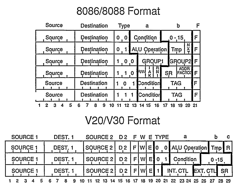
Larger Microcode Format
The V20 had a longer microcode instruction word, 29 bits vs the 21 bit words on the 8088.
The encoding of two source operands is crucial in order to take advantage of the V20's dual internal busses.
The Program Counter and Prefetch Counter
The 8088 maintains a single register called the Program Counter, or PC, which does not actually point to a specific instruction, but instead points to the next byte to be fetched from memory. This is an issue when a CALL needs to be executed - we need the actual address of the next instruction to use in order to save the return address to the stack, which we haven't saved anywhere. To address this, the 8088 has a special microcode subroutine, CORR, which corrects the program counter by subtracting the length of the prefetch queue from PC so that PC is no longer "reading ahead". The CORR routine takes two cycles to execute, one of the few microcode operations that do not execute in a single cycle.
The V20 maintains both a Program Counter and a Prefetch Pointer (PFP) register. The former always points at the start of the next instruction to be executed, while the Prefetch Pointer is free to track ahead, pointing to the next byte to be fetched. Keeping separate registers in this way eliminates the need to correct the value of PC for CALLs, as the proper return address is always available.
Queue Flushing Optimizations
On the 8088, every flow control operation requires two successive microcode operations, SUSPEND and FLUSH. The SUSPEND routine suspends prefetching, and waits for any bus operation in progress to complete before returning. Some time afterwards, a FLUSH operation is executed, which empties the instruction queue and resumes the prefetching process to fetch the first byte at the new code address. By first suspending prefetching and waiting for an idle bus, the 8088 ensures that a code fetch is not in progress when the queue is flushed. Otherwise, an in-progress code fetch could potentially complete after the flush was executed and an incorrect byte would be placed into newly emptied queue.
NEC seems to have combined these two operations into one. It does not directly suspend prefetching during a flow control instruction. This means that when the queue is flushed, a code fetch may be in progress. The flush operation will simply wait for T4 in that case before flushing the queue. This way the in-progress code fetch is discarded as well. This method also maintains compatibility with the 8087.
The Loop Counter
The Loop Counter is a dedicated 16-bit register for tracking remaining iterations of a repetitive instruction such as string operations or shifts. This avoided the requirement to continually decrement the CX/CL register, an activity that cost the 8088 time managing in microcode.
The Halted State
The V20 implements a low-power mode when halted; judicious use of the HLT instruction when active processing is not required (with careful consideration for the V20's interrupt behavior) could drastically reduce power utilization of the chip. This would be very useful for battery-powered applications.
A V20 Opcode Chart
I was unable to find a good chart of V20 opcodes, so I made one. The base data is courtesy of
ref.x86asm.net, with specific modifications made for the V20. It also includes the 8080 instruction set, with data provided by
emulator101.com.
The chart is a work in progress; I will be making updates as I learn more about the V20 and data-mine the CPU tests.
A V20 Test Suite
Besides fuzzing the V20 to investigate its behavior, I have been generating a V20 test suite similar to the
test suite I generated for the Intel 8088, and the histograms in this article are sourced from that data.
The V20 test suite currently encompasses 360 instruction test files, most of which provide 10,000 randomized instruction executions with initial and final register and memory state as well as cycle-by-cycle CPU bus activity. The compressed size of the test suite is 842MB, uncompressed it is over 8GB of JSON.
Some new features of the V20 test set include:
- Nearly 3 million instruction executions spanning 82 million cycles
- Exercise of the V20's prefetch queue, with half of instruction tests executing from a fully prefetched state (Thanks to the magic of opcode 63).
- Per-cycle capture of the V20's multiplexed bus
- Format-compatible with a future V30 test set
- Format-compatible with future interrupt and NMI tests
I hope this serves as a valuable resource for emulator developers. Future goals include test sets for the V20's 8080 emulation mode, as well as full test suites for the 8086, V30, 188 and 186 CPUs.
References


Off topic perhaps, but what is strange about the behaviour of opcode 0x8f (POP, not PUSH) when used with a register operand on the 8088? Those variants were definitely part of the testcases I generated and ran in the development of XTCE, and I don't remember anything strange about them. Though it's possible I just never looked at their non-timing behaviour.
ReplyDeleteSorry, I misspoke. The issue is not merely using it with a register operand, but using it when REG!=0.
DeleteOh, so opcodes like 0x8f 0x08? Aren't they just aliases of the corresponding REG==0? I know that part of opcode space is also used for XOP encodings but that didn't come along until very much later.
Delete